 |


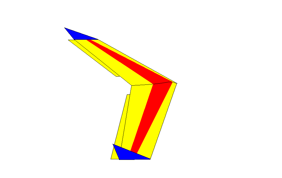
SCORPION
EPP Combat Slope Wing
By Off The Edge Sailplanes
Congratulations on your purchase of the SCORPION
Assembly of the SCORPION is quite straightforward and should be not to difficult for the first time builder. If you have
any problems with the assembly please contact us, a fellow slope flier or your local hobby shop.
We know you will really enjoy flying your new SCORPION, so we will give a money back guaranty if you don’t like it.
OFF THE EDGE SAILPLANES
E-Mail: orders@offtheedge.com.au
Before you begin assembly
1) Check that the two wing halfs, three carbon spars and the two elevons are free from damage.
2) Other equipment that is needed to complete your SCORPION
1. a 2 channel radio (min), but a radio with elevon mixing is preferred
2. 2 Hytec HS81MG servo’s (recommended but std servos will fit)
3. 1 elevon mixer (if using a radio without a mixing function)
4. 3M 77 Spray adhesive
5. 1 roll of fiber filament tape
6. colored packing tap
7. ½ A control horns
8. Polyurethane glue (PU glue)
Assembling The Wings
There are three parts to each wing panel. The wing cores come with the top and bottom beds that they were cut from. These beds are used as jigs in the construction of your SCORPION.
Insert the long carbon spars into the long spar groove on the bottom of the each wing, leaving about an inch sticking out at one end. Run a small bead of PU glue along the length of the spar. Rotate the spar until the glue has coated the spar. Spray the spar with water and rotate again until the glue stars to go milky and then insert the spar fully until it is flush with the root end of the wing. Put a sheet of oven bake paper onto the top wing bed were the wing will sit. Cover the spar with a layer of colored packing tape and put the wings in the beds bottom side up. Put another sheet of oven bake over the bottom of the wing and cover the spar groove with telephone books. The PU glue expands and will fill up the paws in the foam, the telephone books stop the glue from foaming out of the spar groove.
When the glue has cured remove the wings from there beds, remove the tape covering the spar’s. If any glue has foamed out of the spar groove it can be sanded flush with 120 grit sand paper.
Spread 5min epoxy on the two root ends of the wings. Put the two wings half together, making sure that the center spar slots are aligned. Put two pieces of fiber tape on the top and bottom of the wing and put in the beds.
Run a light bead of PU glue in the center spar groove and spray with water. Push the spar into the groove. Run another small bead of PU glue on the top of the spar and spray with water. Cover the spar with tape. Put the wings in the beds and cover with oven bake and telephone books.
Installing the Servos
Plug your servos into the receiver (RX), turn on the transmitter (TX) and then turn on the RX. Center the trims on the TX then center the servo arms by removing the horn from the servo if it is needed.
Check that the servos operate in the correct directions. Disconnect the battery and turn off the TX.
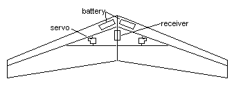
Locate the servo so that it fits between the junction were the spars meet (see diagram). Trace around the servo and with a sharp knife cut the servo hole completely out. The servo should be a snug fit with the servo arm at the top of the wing. Take your sharp knife and cut a 10mm deep line from the servo to the RX, this cut is for the servo lead to sit in. The servo’s can now be glued in with a dab of hot glue (not to much).
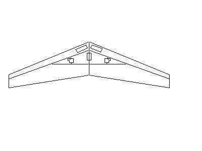
Install the radio
Locate the receiver in the center of the root between the spars, cut a hole deep enough so that the RX (with the servos plugged in), sits flush with the top of the wing. The battery is located in front of the spars.
Mark out the servo holes and cut all the way through to the other side, push the cookie out but don’t throw it away just yet. Check the fit of the servos (should be a snug fit) and the servo arms should be flush with the top of the wing. Measure the gap at the bottom and top of the servos and cut a wafer out of the cookie to fill in the gaps above and below the servo, any excess can be sanded flush. Cut a 10mm deep slit from the servo wire to the receiver and push the servo wire into this cut. The servo and the bottom wafer can now be glued into position with a small amount of hot glue (try not to let the hot glue get to hot as it will melt the foam).
Mark a straight line from the servo arm to about 50mm from the trailing edge, cut or melt a channel just wide enough and deep enough to sit the pushrod in flush with the top of the wing, the outer part of the pushrod can be hot glued into position leaving about 10mm protruding from the cannel at the trailing edge.
Taping the Wing
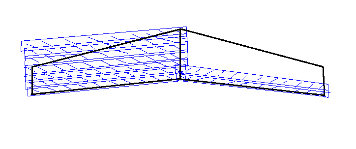
Vacuum the dust from the cores, beds and work bench. Make sure that all of the radio gear is covered with masking tape before spraying with 3M 77. Lay the wing in the top bed, bottom-side up. Apply a coat of 3M 77 spray adhesive to the entire bottom wing and allow to dry for at least 5 minutes before applying the fiber strapping tape. (See drawing for tapping configuration)

Repeat this procedure for the other side.
Covering with Colored Tape
It is a good idea to have the top and bottom of the wing in contrasting colors and patterns to make it easier to see.
Spray the bottom of the wing with 3m 77 making sure to spray the LE and TE, put it back into the top bed and let dry for 5 minutes. Start applying the colored tape at the trailing edge of the wing and working forward to the leading edge, applying strips of tape from the tip to at least 30mm past the center of the wing, over lapping the tape by 10mm all the way. Cut the excess tape at the leading edge 20mm past the LE and carefully rap around the LE.
Spray the top of the wing and repeat the taping procedure again working from the TE to the LE. Finish the LE with a single piece of tap wrapped around the LE.
Prepare and attach the Elevons
Hold the elevons together and sand them until they are identical. Trim the ends to match the angle of the wing tip. Sand a 45 degree angle into the front of the elevon then completely cover the elevons with fiber tape and then colour tape.
Position the elevon at the trailing edge of the wing and apply a tape hinge the full length of each elevon with fiber tape to the top of the wing and elevon as shown. Swing the elevon to the top of the wing and lay flat. Complete the hinge with another full length strip of fiber tape on the bottom as shown.
Attach the Elevons to the Servos
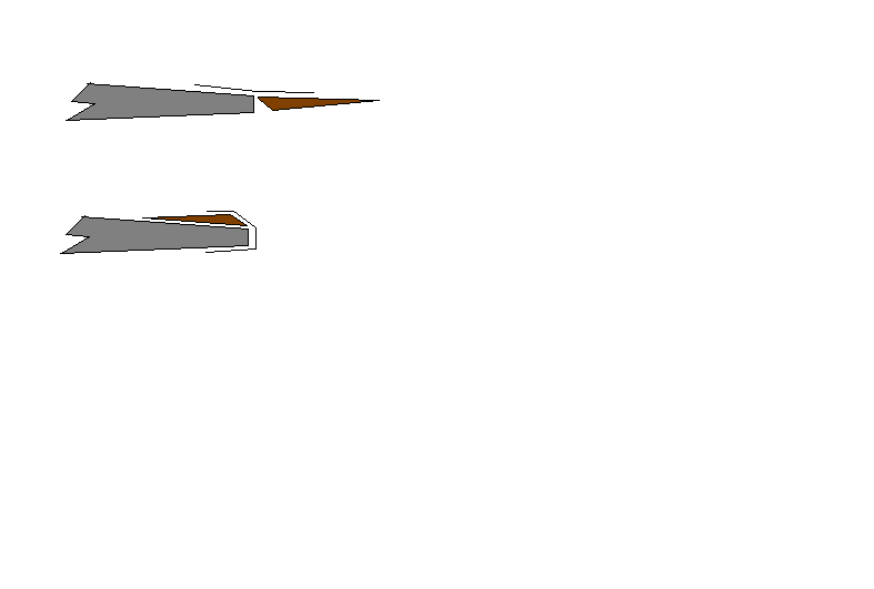
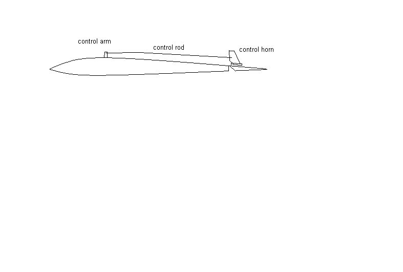
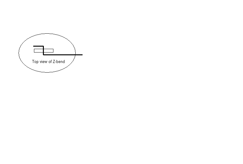
Position the control horns on the elevon directly behind the servo control arm with the holes of the horn inline with the hinge line. Mark the position of the control horns. Drill two holes with a 3/32” drill for each control horn. Install the control horns onto the elevons. Attach the control rods to the 2nd or 3rd hole from the of the control horn and attach the threaded control rods. Make a 10 degree bend in the control rods 1 inch behind the servo to prevent binding. Turn on your transmitter and then turn on the receiver in the plane, center the servos and servo trims then turn off the receiver and transmitter. With the rear of the elevon raised approximately 5mm, mark the position of the servo control arm on to the control rod and make a Z-bend by making two 90 degree bends in the control rod. Push the rod through the top servo arm. Some servo arms have small holes that the control rod may not fit through, if this is the case the servo arm will have to be drilled out to fit the control rod to a snug fit (without slop).
Attaching the Winglets
Attach the winglets by putting a piece of fiber tape through the slot to the top of the wing and wrap it around to the bottom of the wing. Add one more piece of tape length ways to the bottom of the winglet onto the bottom of the wing.
Balancing
With a pen, mark a small line 180mm back from the tip of the nose (this is the CG and may vary depending on flying stiles). Tape a round pen or pencil over the CG line. Place the wing (top side up) on a flat surface. Add lead weight to the nose until the wing balances momentarily on the pen. When the balance is set, tape the lead weight to the nose on the bottom of the wing.
Setting trim and throws
With the TX on and the plane turned on (in that order), set the elevon neutral setting by laying a straight edge under the wing at the trailing edge. The elevons should appear to have a few degrees of reflex (up elevator).
Move the transmitter aileron stick to the left, the left elevon should go up and the right goes down, moving the stick to the right should reverse the elevons.
The total aileron movement should be set a 20mm up and 20mm down.
Move the transmitter elevator stick down and both elevons should go up, by moving the stick up, both elevons should go down.
The total elevator movement should be set a 15mm up and 15mm down.
You are now set to have fun with your Scorpion. It is a good idea to test fly your new wing in a flat park to set any fine control surface adjustments and CG.
If you are new to RC slope flying than it is a good idea to ask for help from someone who is experienced, the slope souring community is a very friendly mob and are very willing to help new flyers to the hobby.
Good luck and good flying.
Glenn & Rick
Off The Edge Sailplanes
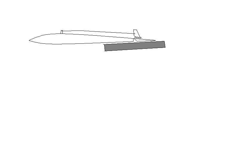
Center Fin
(Optional)
The center fin is used when speed is required, as it has less drag then the two corlfute tiplets.
Mount the center wing mount after you have covered the wing with the strapping tape and before covering with the colored tape.
Start by sanding one side of the corflute mount, spray the mount and the underside of the wing (where the mount is mounted) with 3M77. Using a pushrod in the center flute of the mount, line up the pushrod with the center line of the wing and push the two glued surfaces firmly together. Spray the area with 3M77 again and cover the mount and 50mm each side of the mount with fiber tape.
Cover the fin with colored tape or iron on film. When the plane is completed, the fin can be pushed into the center flute of the mount.